Hydraulic Clutches Overview: Design, Working Principles, and Industrial Applications
Hydraulic clutches are mechanical devices that use hydraulic pressure to engage or disengage the transmission of rotational power between a driving source and a driven component.
They are used in industrial machinery, material handling equipment, manufacturing systems, and heavy-duty mechanical applications where controlled power transmission is necessary. Hydraulic clutch manufacturers develop different designs according to operating loads, machine configurations, and control requirements.
Unlike a purely mechanical clutch that relies on direct mechanical linkages, a hydraulic clutch uses pressurized fluid to transfer force to an actuator or operating mechanism. This arrangement can simplify control and allow clutch engagement to be managed from a separate control point. The exact design depends on whether the clutch is intended for intermittent operation, repeated engagement, or specialized industrial processes.
Industrial hydraulic clutch systems generally contain a clutch assembly, hydraulic actuator, fluid passages, seals, and control components. Some configurations also include sensors and electronic controls that help coordinate clutch operation with other machine functions.
Basic Design and Main Components
A hydraulic clutch system combines mechanical and hydraulic components. Each part performs a specific function within the power transmission process.
Clutch assembly: Contains the friction surfaces or other coupling elements that connect the driving and driven components.
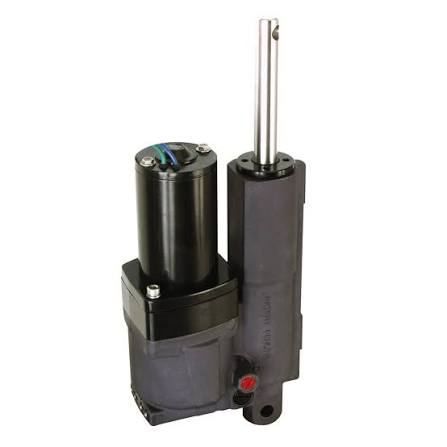
Hydraulic actuator: Converts fluid pressure into mechanical movement that operates the clutch.
Pump and fluid circuit: Supply and direct hydraulic fluid where required by the system design.
Valves and controls: Regulate pressure and fluid movement to manage engagement and disengagement.
Seals and passages: Help contain hydraulic fluid and direct it through the intended circuit.
The arrangement varies between clutch types. Some systems use hydraulic pressure to engage the clutch, while others use hydraulic pressure to release a spring-engaged mechanism.
How Hydraulic Clutches Work
The working principle begins when a control signal or mechanical input activates the hydraulic circuit. Fluid pressure moves the actuator, which applies or releases force on the clutch mechanism. This changes the connection between the driving and driven components.
When the clutch engages, torque can pass from the input shaft to the output shaft. When it disengages, the transmission of torque is interrupted or reduced according to the clutch design. Correct pressure, suitable fluid, and properly maintained components help the mechanism operate as intended.
Hydraulic power transmission clutches are not identical to hydraulic torque converters or fluid couplings. A clutch mechanically connects or disconnects rotating components, while a fluid coupling transfers torque through fluid movement and generally does not provide the same direct mechanical separation.
Importance
Hydraulic clutches play an important role in equipment that requires controlled starting, stopping, or transmission of rotational power. They can be found in industrial presses, processing machinery, conveyor drives, marine equipment, agricultural machinery, and selected heavy-duty transmission systems.
Their operation affects machine coordination, production continuity, and operator safety. In systems with substantial rotating loads, the ability to control engagement can help manage how power reaches the driven equipment.
Industrial Applications
Heavy duty hydraulic clutches are used in applications where the equipment must transmit substantial torque or operate under demanding conditions. Their suitability depends on the clutch's rated torque, operating speed, thermal capacity, duty cycle, and surrounding environment.
Common applications include:
Manufacturing equipment: Connecting drive motors to production machinery.
Material handling: Controlling power transmission in selected conveyor and lifting systems.
Agricultural machinery: Managing mechanical drive connections in compatible equipment.
Marine applications: Supporting power transmission in certain propulsion and auxiliary systems.
Industrial processing: Coordinating rotating equipment with different operating stages.
Not every hydraulic clutch is appropriate for every application. Load characteristics, engagement frequency, available hydraulic pressure, and installation requirements influence the selection.
Hydraulic Clutches Compared with Other Systems
Industrial clutch and brake systems may combine clutch mechanisms with brakes to control rotation and bring machinery to a stop. Although both components influence motion, they perform different functions: a clutch transmits or interrupts torque, while a brake resists motion or stops a rotating component.
Pneumatic and hydraulic clutch systems also differ in how they generate operating force. Pneumatic systems use compressed air, whereas hydraulic systems use pressurized liquid. The choice depends on the required force, response characteristics, available infrastructure, environmental conditions, and machine design.
| Feature | Hydraulic Clutch | Pneumatic Clutch | Mechanical Clutch |
|---|---|---|---|
| Operating medium | Pressurized liquid | Compressed air | Mechanical linkage or force |
| Force control | Hydraulic pressure | Air pressure | Mechanical input |
| Typical consideration | Fluid condition and sealing | Air quality and pressure stability | Linkage wear and adjustment |
| Common applications | Industrial drives and heavy machinery | Selected automated machinery | Vehicles and general machinery |
Maintenance and Operating Challenges
Hydraulic clutches can experience problems caused by fluid contamination, worn seals, leakage, overheating, incorrect pressure, or friction material deterioration. Symptoms may include delayed engagement, slipping, unusual noise, or inconsistent operation.
Maintenance procedures depend on the equipment manufacturer's documentation and the operating environment. Regular inspections, appropriate fluid selection, pressure checks, and monitoring of operating temperature can help identify developing faults. Work on pressurized systems requires suitable isolation procedures because stored hydraulic pressure can cause injury.
Recent Updates
Developments in hydraulic clutch technology from 2024 through 2026 generally reflect broader changes in industrial automation, condition monitoring, and energy management. Hydraulic mechanisms remain relevant in applications that require substantial operating force, while electronic controls and monitoring tools are becoming more closely integrated with industrial equipment.
Electronic Controls and Condition Monitoring
Modern machinery may use electronic controllers to coordinate clutch engagement with motor speed, load conditions, and other machine functions. Sensors can monitor variables such as pressure, temperature, vibration, or operating cycles when these features are included in the system.
This information can help maintenance teams identify changes in equipment behavior. However, monitoring capabilities vary, and sensor readings do not automatically establish the cause of a mechanical fault.
Design Improvements and System Integration
Current engineering work includes attention to sealing materials, friction characteristics, thermal management, and more precise control of hydraulic pressure. These areas are relevant to advanced industrial machinery, particularly where repeated engagement produces heat and mechanical stress.
Hydraulic clutch actuator systems may also be integrated with programmable controllers and automated manufacturing systems. Such integration can coordinate machine sequences, although the overall performance depends on system design, calibration, and maintenance.
Replacement and Compatibility Considerations
Hydraulic clutch replacement assemblies must match the original equipment's mechanical dimensions, torque requirements, operating speed, pressure range, and mounting arrangement. A physically similar assembly may not function correctly if its internal characteristics or control requirements differ.
Hydraulic clutch suppliers and manufacturers may document these specifications through technical drawings, operating manuals, and product data sheets. Custom industrial hydraulic clutches may be designed for unusual mounting arrangements or specific duty cycles, but their suitability requires engineering evaluation.
Tools and Resources
Several technical resources can help explain hydraulic clutch design and support equipment assessment.
Engineering Documents and Calculation Tools
Manufacturer manuals, hydraulic circuit diagrams, and component specifications describe how a clutch operates within a particular machine. Torque calculators and rotational-speed references can help users understand basic transmission requirements, although they do not replace detailed engineering analysis.
Useful resources include:
Hydraulic circuit diagrams for understanding fluid flow and actuator operation.
Torque and rotational-speed calculators for preliminary mechanical calculations.
Equipment manuals for pressure limits, fluid specifications, and inspection procedures.
Technical data sheets for comparing dimensions, ratings, and mounting arrangements.
Maintenance checklists for recording leakage, temperature, operating noise, and inspection findings.
Technical Standards and Documentation
Technical publications from organizations such as the International Organization for Standardization (ISO) provide information about relevant mechanical and hydraulic engineering standards. The applicable standard depends on the equipment category and intended application.
Documentation from hydraulic component manufacturers can also explain actuator designs, pressure ratings, seal compatibility, and operating limitations. These references are particularly relevant when evaluating hydraulic clutch replacement assemblies or integrating a clutch into an existing machine.
FAQs
What are industrial hydraulic clutch systems used for?
Industrial hydraulic clutch systems control the transmission of rotational power in machinery. They are used in compatible manufacturing equipment, material handling systems, processing machinery, and other industrial drives.
How do hydraulic clutch actuator systems work?
Hydraulic clutch actuator systems use pressurized fluid to move a mechanism that engages or disengages the clutch. The actuator's movement depends on the circuit design, pressure, and control arrangement.
What should be considered when selecting heavy duty hydraulic clutches?
Important factors include torque capacity, rotational speed, engagement frequency, heat generation, hydraulic pressure, mounting dimensions, and operating environment. The clutch must also be compatible with the machine's drive system.
When are hydraulic clutch replacement assemblies required?
Replacement may be necessary when a clutch is damaged, worn beyond acceptable limits, or no longer operates according to its specifications. Compatibility with the original equipment must be checked before installation.
What is the difference between pneumatic and hydraulic clutch systems?
Pneumatic clutch systems use compressed air to generate operating force, while hydraulic clutch systems use pressurized liquid. Their suitability depends on required force, response, operating conditions, and the equipment's existing infrastructure.
Conclusion
Hydraulic clutches use fluid pressure to control mechanical engagement and transmit rotational power in industrial and other heavy-duty applications. Their design combines hydraulic components, actuators, control mechanisms, and clutch assemblies to meet different operating requirements. Recent developments emphasize electronic integration, condition monitoring, and improved control of industrial machinery. Proper selection, compatible components, and appropriate maintenance remain important factors in reliable operation.

Related Post...
Vacuum Pads Guide: Types, Materials, and Industrial Applications
Updated: October 19, 2026
Read More
Weather Instruments Guide: Understanding Tools for Measuring Atmospheric Conditions
Updated: October 19, 2026
Read More